How to Draw Context Diagram in Visual Paradigm
Creating diagrams
You can create diagrams to help visualize what you did, what you are doing and what you demand to do on your target system or application. There are different types of diagrams to fulfill different needs, such as UML diagrams, requirements capturing, database modeling, business organisation procedure modeling and others.
Creating a diagram
Through the toolbar
- Select Diagram > New from the application toolbar.
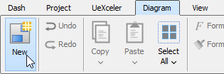
Create diagram through toolbar - In the New Diagram window, select the blazon of diagram to create.
- Click Next.
- Enter the diagram name and description.
- You tin can set the Location, which is the model for storing the diagram. Note that if a diagram is opened in background and if that diagram is being stored in a model, nosotros will automatically select that model as Location.
- Click OK.
Through shortcut fundamental
You can printing Ctrl-Northward to create a diagram.
Cartoon shapes
After creating a new diagram, diagram elements can be created besides through the diagram toolbar. In this department, these techniques of cartoon shapes volition exist explicated:
- Creating Shapes
- Creating Connectors
- Creating Self-Connection
Creating shapes
To create a shape, click a diagram element from the diagram toolbar and click it on the diagram pane for creating. The generated chemical element will appear with the default size.
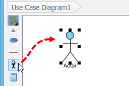 |
| Click an role player on the diagram pane |
For defining a specific shape size, drag a specific boundary with the mouse subsequently clicking a diagram chemical element from the diagram toolbar.
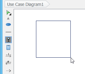 |
| Drag a specific purlieus with the mouse |
Alternatively, a diagram element tin be created by dragging the diagram chemical element and and so dropping it on the diagram pane.
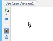 |
| Elevate and drib to create a shape |
In addition, you tin add together a shape through the popular-upward menu of diagram. Correct click on the diagram background, select Add Shape and so a specific shape from the pop-up carte.
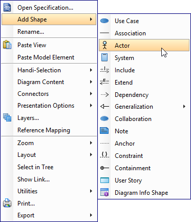 |
| Create a shape through the pop-up menu of diagram |
Enter the name of the shape and printing Enter to ostend. When naming a shape, yous tin enter the name of an existing model element to create an auxiliary view of that chemical element. We call this step to 'reuse' a model element. If you desire to reuse an element just are unclear nearly its name, press Ctrl-Space to toggle the completion list and select the element in that location. You lot may also add together a glossary term into shape name. Just press Ctrl-Space when naming a shape, then press Ctrl-Space again to switch to the term pick list. Of course, this will work only when term has been divers in your projection.
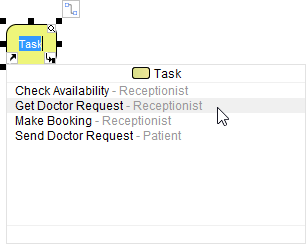 |
| To reuse a BPMN job |
Creating connectors
To create a connector, select the desired connector from the diagram toolbar, drag the connector from the source shape to the destination shape. Since Visual Paradigm provides a continuous UML syntax checking, if you create an invalid connectedness, a stop sign will be pop-out. For instance, you are not allowed to connect an thespian and a use case with a generalization relationship.
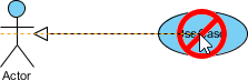 |
| An invalid connection is created |
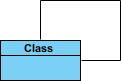
If the connectedness is valid, a greyness rectangle surrounding the destination shape can exist seen.
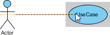 |
| A valid connection is created |
Moreover, connectors can be created through resource icons:
- Motion the mouse pointer over the source shape.
- Press on the Resource Catalog button and drag it out.
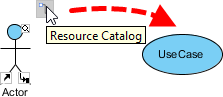
Resource Itemize
- Release the mouse push on the target shape..
- Select the desired the connector type from Resource Catalog.
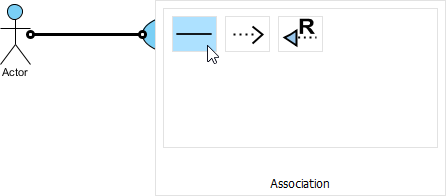
Select Association to be created
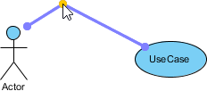
If you release the mouse on an empty space, a new shape can be created with a connector.
Creating self-connexion
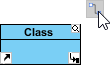
Some shapes can brand a connection for itself, for example, Self-Clan of a Class in grade diagram and Self-Link of an Object in advice Diagram.
 |
| Course with cocky association |
To create a self-connectedness:
- Motion the mouse pointer to the shape.
- Click on the Resource Catalog push.
To utilise Resource Catalog
- Select the self connector to exist created.
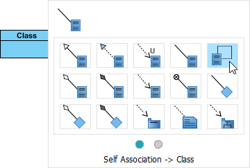
Create a self assocaition
Creating turning point on connector
A turning point is a betoken on a connector where a bending takes place. To create a turning bespeak on an existing connector, press on the connector and drag to bend the connector.
 |
| Create turning indicate on existing connector |
You lot tin can also create a turning signal when creating a shape through Resource Catalog. When dragging out Resource Itemize button, printing the Shift button at the identify you want to create the turning point.
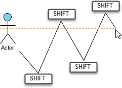 |
| Create turning points when creating shape by dragging Resource Itemize |
Resources-centric interface
Visual Paradigm is the first vendor to introduce the resource centric diagramming interface. The resource centric interface greatly improves the efficiency of modeling. You lot don't accept to traverse between the toolbar and the diagram to create diagram elements, make connections and modify the diagrams. The resources axial interface can make sure the modeler is able to create a diagram with right syntax more quickly.
There are tree types of resource icons:
- Connection Resources
- Manipulation Resources
Connection resource (Resources Catalog)
It is designed for creating elements and making connections.
| |
| To associate an actor with use case with Resource Catalog |
Manipulation resource
You tin utilise Manipulation Resource to alter properties or appearance of elements. For example, yous tin can show or hide compartments, add references, add sub-diagram and fit size.
 |
| Fit size through manipulation resource |
Cartoon freehand shapes
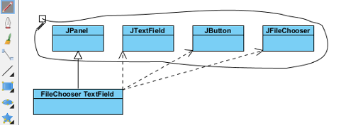
Freehand shape is a kind of general graphic shapes. Pen shapes, pencil shapes, and some regular shapes like circumvolve, rectangle and pointer are available. Freehand shape can be used for annotating diagram. For case, y'all tin can use freehand shapes to emphasize some shapes.
A specific shape can be highlighted with a pencil shape.
 |
| Pencil |
An outstanding text can be shown with word fine art.
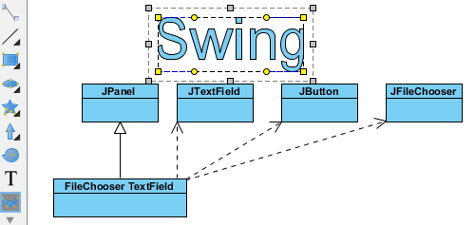 |
| Word Art |
A freehand shape style can be formatted in order to address your information.
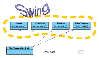 |
| Styled freehand shapes |
Changing bundle header
You can specify the parent package of whatever diagram through Bundle Header.
Package header when diagram created
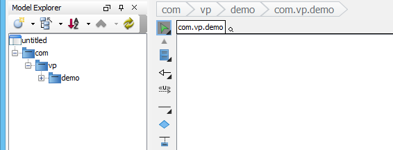
When a diagram is created, the bundle header will be unfolded as it allows y'all to specify the parent package of the diagram. Specify the package by entering the fully qualifier name of the packet.
 |
| Specify parent package in package header |
After entering the name of parent package, yous will notice that the diagram name is the same equally the name of parent bundle.
 |
| Diagram name will exist same every bit fully authorize of paret parcel |
The diagram name can exist renamed. However, the proper noun of parent package won't exist changed to follow the diagram name.
You can open specification of parent package by pressing the Open up Specification button on the right-paw side of the parent package name.
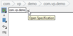 |
| Open up Specification |
You can rename the parent package of the diagram by double clicking on it.
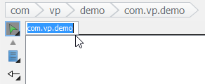 |
| Double click on the parent package |
A new parcel will exist created if you enter a completely new package name. If the previous parent package does non contain elements, information technology will be deleted. That ways the clarification (or other properties) of previous parent package volition be lost.
A package header can be either shown or hidden through the pop-upward carte of diagram. Right click on the diagram background and select Presentation Options > Prove Bundle Header from the pop-up bill of fare.
Justifying shape's name
A shape'southward proper name is aligned with eye horizontally or top and middle vertically, depending on the feature of shapes. However, the shape's name can be realigned. Even if a language, such equally Modern Hebrew, that is written from the correct to the left can be displayed on a shape clearly.
To adjust the explanation position for all shapes in a diagram:
- Right click on the diagram groundwork, select Presentation Options > Explanation Placement and then select a specific alignment option from the pop-up menu.
- Every bit a outcome, all shapes' proper noun in the whole diagram will plough into the alignment option y'all set previously.
All shapes' names turn into middle right
Apart from the whole diagram setting, a specific shape tin also be set up:
- Right click on a shape, select Presentation Options > Explanation Placement and then select a specific alignment option from the pop-up card.
- As a consequence, the specific shape will turn into the alignment option yous set previously.
In addition to the current diagram, future diagrams can likewise be set:
- Select Window > Project Options... from the toolbar.
- In the Project Options window, select the Diagramming category, check an selection out of Caption Placement section under the Advent tab.
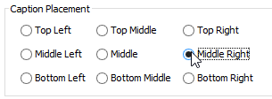
Check an alignment option in the Projection Options window
Exceptions
Although most shapes' proper noun tin can be justified, some are exceptional. Two main kinds of shapes that their names cannot be justified are introduced as follows:
On one hand, shapes neither with floating name characterization (freely movable) nor with a characterization outside the shapes can exist justified. Histrion, Initial Pseudo Node and BP Commencement Events are examples of this kind of shape.
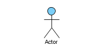 |
| Floating proper noun label |
On the other hand, the names of container shapes are non available for positioning. Since their "bodies" are used for containing other shapes, thereby, they take a limited scope of displaying names. Package, State and System are example of this kind of shape.
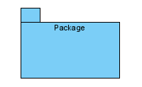 |
| Container shape |
Enabling and disabling minimum shape size
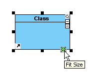
Since all shapes take their own default minimum size, users are not immune to resize them to smaller than the minimum size. The default setting helps to ensure those compact shapes are articulate enough to be seen on a diagram nether normal circumstance. The minimum size of a shape tin be determined by pressing its fit size push.
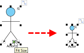 |
| The minimum size of a shape can be adamant by pressing its fit size button |
Now, it is possible to disable such setting, so that shapes can exist resized to extremely small in size, despite their minimum size:
- To disable the function of the minimum size checking, select Window > Projection Options... from the toolbar.
- In the Project Options dialog box, select the Diagramming category and uncheck Enable minimum shape size when resizing shape under Appearance tab. Click OK to confirm.
- Afterward that, y'all tin can resize a shape to the size as small-scale as you desire.
- Furthermore, select other shapes and select an selection from the drop-downwardly bill of fare of resource icon Aforementioned Width.
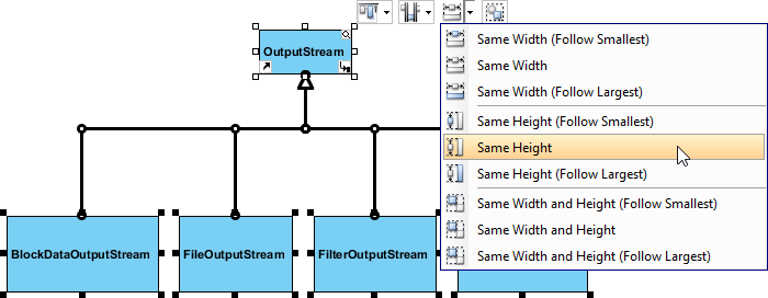
Make all shapes in same acme
- As a result, other shapes will turn into the same size as the shape you have done previously.
All shapes are turned into the same small height
Undo and redo
During the process of editing a diagram, you lot may make some devil-may-care mistakes, such as accidentally deleting a shape. You lot tin can use the Undo part to cancel the previous activeness. On the contrary, you may re-perform the activeness through the Redo function. Notation that the undo/redo feature in Visual Paradigm is diagram based.
Disengage
You can coil dorsum undesirable changes past performing Undo. Disengage role tin be executed in the post-obit iii means:
- Select Diagram > Undo
 from the toolbar.
 - Press Ctrl-Z.
Redo
This characteristic is to re-perform actions that have but been undone. Redo part can be executed in the following 3 ways:
- Select Diagram > Redo
 from the toolbar.With
 - Press Ctrl-Y.
Showing name for undo and redo action
It's hard for us to recall all actions nosotros accept done previously. Past Visual Paradigm, we can recall the deportment we have done earlier.
You lot can detect an action name of undo/ redo on toolbar button'due south tooltip. Move the mouse over the Undo or Redo push and then a tooltip with Undo/ Redo action name will appear.
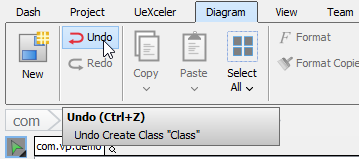 |
| Toolbar button'due south tooltip shows undo/redo activity |
Related Resources
The following resources may help you lot to larn more about the topic discussed in this folio.
- New to Visual Paradigm? We have a lot of UML tutorials written to help you lot get started with Visual Paradigm
- Visual Paradigm on YouTube
- Visual Image Know-How - Tips and tricks, Q&A, solutions to users' bug
- Contact us if you need whatsoever aid or take any proffer
How to Draw Context Diagram in Visual Paradigm
Source: https://www.visual-paradigm.com/support/documents/vpuserguide/1283/27/6243_creatingdiag.html
0 Response to "How to Draw Context Diagram in Visual Paradigm"
Post a Comment