What Happens to the Light Rays When They Hit the Specimen?
iii.1: How Microscopes Work
- Page ID
- 31770
Learning Objectives
- Identify and define the characteristics of electromagnetic radiation (EMR) used in microscopy
- Explicate how lenses are used in microscopy to manipulate visible and ultraviolet (UV) light
- Draw historical developments and individual contributions that led to the invention and evolution of the microscope
- Compare and contrast the features of simple and compound microscopes
- Identify and describe the parts of a brightfield microscope
- Summate total magnification for a chemical compound microscope
- Describe the distinguishing features and typical uses for diverse types of light microscopes, and electron microscopes.
Clinical Focus: part 1
Cindy, a 17-year-one-time counselor at a summer sports campsite, scraped her knee playing basketball game ii weeks ago. At the time, she thought it was only a pocket-size abrasion that would heal, similar many others earlier it. Instead, the wound began to look similar an insect bite and has continued to get increasingly painful and swollen.
The campsite nurse examines the lesion and observes a large amount of pus oozing from the surface. Concerned that Cindy may have developed a potentially aggressive infection, she swabs the wound to collect a sample from the infection site. Then she cleans out the pus and dresses the wound, instructing Cindy to go on the area clean and to come dorsum the adjacent 24-hour interval. When Cindy leaves, the nurse sends the sample to the closest medical lab to be analyzed under a microscope.
Exercise \(\PageIndex{1}\)
What are some things we tin can larn about these bacteria by looking at them under a microscope?
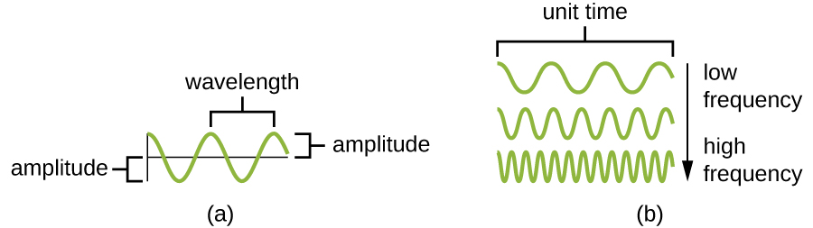
Visible light consists of electromagnetic waves that behave like other waves. Hence, many of the properties of light that are relevant to microscopy can be understood in terms of lite's beliefs as a wave. An important property of lite waves is the wavelength, or the distance between i peak of a moving ridge and the next meridian. The height of each top (or depth of each trough) is called the amplitude. In dissimilarity, the frequency of the wave is the rate of vibration of the wave, or the number of wavelengths within a specified time period (Figure \(\PageIndex{one}\)).
Interactions of Low-cal
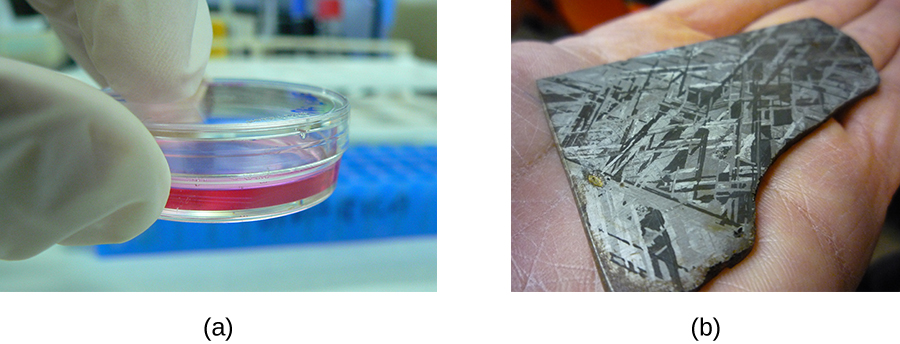
Low-cal waves interact with materials by existence reflected, absorbed, or transmitted. Reflection occurs when a wave bounces off of a material. For example, a crimson slice of fabric may reflect red low-cal to our eyes while absorbing other colors of light. Absorbance occurs when a cloth captures the energy of a light wave. In the case of glow-in-the-dark plastics, the free energy from light can be absorbed and then later re-emitted as another form of phosphorescence. Manual occurs when a wave travels through a textile, like lite through glass (the process of transmission is called transmittance). When a material allows a large proportion of light to be transmitted, it may do then because it is thinner, or more transparent (having more than transparency and less opacity). Effigy \(\PageIndex{two}\) illustrates the difference betwixt transparency and opacity.
Exercise \(\PageIndex{2}\)
- If a light wave has a long wavelength, is information technology probable to have a low or loftier frequency?
- If an object is transparent, does it reverberate, absorb, or transmit light?
Lenses and Refraction
In the context of microscopy, refraction is perhaps the most important behavior exhibited by light waves. Refraction occurs when light waves change direction as they enter a new medium (Effigy \(\PageIndex{iii}\)). Unlike transparent materials transmit light at unlike speeds; thus, low-cal can alter speed when passing from one material to some other. This change in speed usually likewise causes a change in direction (refraction), with the degree of change dependent on the angle of the incoming light.
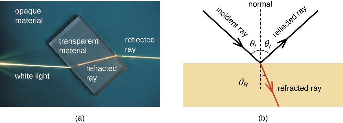
The extent to which a textile slows transmission speed relative to empty space is called the refractive index of that textile. Large differences between the refractive indices of two materials volition effect in a large amount of refraction when low-cal passes from 1 fabric to the other. For example, low-cal moves much more slowly through water than through air, so light entering water from air can change management greatly. We say that the water has a higher refractive alphabetize than air (Effigy \(\PageIndex{4}\)).

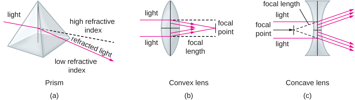
When light crosses a boundary into a textile with a higher refractive alphabetize, its direction turns to be closer to perpendicular to the purlieus (i.e., more toward a normal- the aforementioned angle- to that purlieus; Figure \(\PageIndex{5}\)). This is the principle backside lenses. We tin think of a lens as an object with a curved boundary (or a collection of prisms) that collects all of the light that strikes it and refracts it so that it all meets at a single point chosen the focus bespeak (or image point). A convex lens tin can exist used to magnify considering it tin can focus at closer range than the human eye, producing a larger paradigm. Concave lenses and mirrors tin as well be used in microscopes to redirect the low-cal path. Figure \(\PageIndex{5}\) shows the focal bespeak (the paradigm indicate when low-cal entering the lens is parallel) and the focal length (the distance to the focal point) for convex and concave lenses.
The human eye contains a lens that enables us to meet images. This lens focuses the low-cal reflecting off of objects in front of the eye onto the surface of the retina, which is like a screen in the dorsum of the centre. Artificial lenses placed in front of the eye (contact lenses, glasses, or microscopic lenses) focus light earlier information technology is focused (again) by the lens of the eye, manipulating the image that ends up on the retina (east.g., past making information technology appear larger).
Images are commonly manipulated by controlling the distances between the object, the lens, and the screen, too as the curvature of the lens. For example, for a given amount of curvature, when an object is closer to the lens, the focal points are farther from the lens. As a consequence, it is oftentimes necessary to manipulate these distances to create a focused image on a screen. Similarly, more curvature creates image points closer to the lens and a larger image when the image is in focus. This property is often described in terms of the focal distance, or distance to the focal point.
Exercise \(\PageIndex{3}\)
- Explain how a lens focuses light at the paradigm point.
- Name some factors that touch on the focal length of a lens.
Electromagnetic Spectrum and Color
Visible light is merely one form of electromagnetic radiation (EMR), a type of energy that is all effectually the states. Other forms of EMR include microwaves, Ten-rays, and radio waves, among others. The different types of EMR fall on the electromagnetic spectrum, which is defined in terms of wavelength and frequency. The spectrum of visible calorie-free occupies a relatively small range of frequencies between infrared and ultraviolet light (Effigy \(\PageIndex{half dozen}\)).
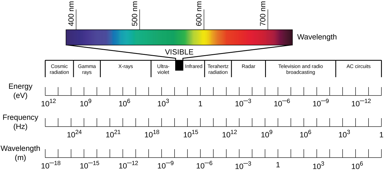
Whereas wavelength represents the distance between adjacent peaks of a light wave, frequency, in a simplified definition, represents the rate of oscillation. Waves with college frequencies have shorter wavelengths and, therefore, have more oscillations per unit of measurement fourth dimension than lower-frequency waves. Higher-frequency waves as well incorporate more energy than lower-frequency waves. This energy is delivered as elementary particles called photons. Higher-frequency waves deliver more energetic photons than lower-frequency waves.
Photons with different energies interact differently with the retina. In the spectrum of visible light, each color corresponds to a particular frequency and wavelength (Figure \(\PageIndex{6}\)).The lowest frequency of visible light appears as the colour red, whereas the highest appears as the color violet. When the retina receives visible light of many unlike frequencies, we perceive this as white light. Even so, white light can be separated into its component colors using refraction. If nosotros pass white light through a prism, different colors will exist refracted in different directions, creating a rainbow-like spectrum on a screen behind the prism. This separation of colors is chosen dispersion, and it occurs because, for a given material, the refractive index is different for different frequencies of calorie-free.
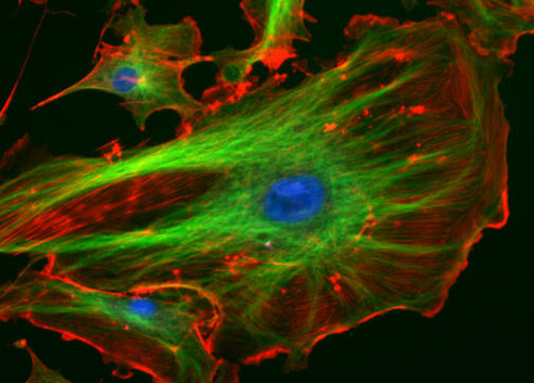
Sure materials tin refract nonvisible forms of EMR and, in effect, transform them into visible light. Certain fluorescent dyes, for instance, blot ultraviolet or blue light and so use the energy to emit photons of a different color, giving off light rather than simply vibrating. This occurs because the energy absorption causes electrons to jump to higher free energy states, after which they then nigh immediately autumn dorsum downwards to their ground states, emitting specific amounts of energy as photons. Non all of the energy is emitted in a given photon, so the emitted photons will be of lower free energy and, thus, of lower frequency than the captivated ones. Thus, a dye such as Texas blood-red may exist excited past blueish light, but emit cerise light; or a dye such equally fluorescein isothiocyanate (FITC) may absorb (invisible) high-energy ultraviolet light and emit dark-green lite (Effigy \(\PageIndex{vii}\)). In some materials, the photons may be emitted post-obit a delay after assimilation; in this instance, the procedure is called phosphorescence. Glow-in-the-night plastic works by using phosphorescent material.
Exercise \(\PageIndex{4}\)
- Which has a higher frequency: red light or greenish light?
- Explain why dispersion occurs when white low-cal passes through a prism.
- Why do fluorescent dyes emit a different colour of light than they absorb?
Magnification, Resolution, and Dissimilarity
Microscopes magnify images and use the backdrop of calorie-free to create useful images of small objects. Magnification is divers as the power of a lens to overstate the image of an object when compared to the existent object. For case, a magnification of 10⨯ means that the paradigm appears x times the size of the object as viewed with the naked eye.
Greater magnification typically improves our power to see details of pocket-size objects, but magnification lonely is non sufficient to make the most useful images. It is often useful to enhance the resolution of objects: the ability to tell that two dissever points or objects are separate. A low-resolution epitome appears fuzzy, whereas a high-resolution image appears sharp. Two factors bear upon resolution. The start is wavelength. Shorter wavelengths are able to resolve smaller objects; thus, an electron microscope has a much higher resolution than a light microscope, since it uses an electron axle with a very brusk wavelength, every bit opposed to the long-wavelength visible light used by a light microscope. The 2nd factor that affects resolution is numerical aperture, which is a measure of a lens's power to get together light. The higher the numerical aperture, the improve the resolution.
Fifty-fifty when a microscope has high resolution, it can be hard to distinguish modest structures in many specimens because microorganisms are relatively transparent. It is often necessary to increment contrast to detect unlike structures in a specimen. Various types of microscopes utilise different features of light or electrons to increment contrast—visible differences betwixt the parts of a specimen. Additionally, dyes that bind to some structures but non others can be used to improve the contrast between images of relatively transparent objects.
Exercise \(\PageIndex{5}\)
- Explain the deviation between magnification and resolution.
- Explain the difference between resolution and contrast.
- Name ii factors that affect resolution.
The Early Microscope
Some of the cardinal characteristics and functions of microscopes can be understood in the context of the history of their utilize. Italian scholar Girolamo Fracastoro is regarded as the first person to formally postulate that illness was spread by tiny invisible seminaria, or "seeds of the contagion." In his book De Contagione (1546), he proposed that these seeds could attach themselves to certain objects (which he called fomes [cloth]) that supported their transfer from person to person. All the same, since the applied science for seeing such tiny objects did non yet exist, the existence of the seminaria remained hypothetical for a piddling over a century—an invisible globe waiting to exist revealed.
Who Invented the Microscope?
While Antonie van Leeuwenhoek and Robert Hooke generally receive much of the credit for early on advances in microscopy, neither tin claim to be the inventor of the microscope. While van Leeuwenhoek is credited with the discovery of microorganisms, others before him had contributed to the development of the microscope. These included the Italian astronomer Galileo Galilei, who used a chemical compound microscope to examine insect parts . Whereas van Leeuwenhoek used a simple microscope, in which light is passed through but 1 lens, Galileo'south compound microscope was more sophisticated, passing light through two sets of lenses.
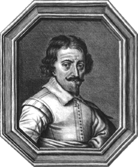
Some fence that this designation of inventor should belong to Hans and Zaccharias Janssen, Dutch spectacle-makers who may have invented the telescope, the simple microscope, and the compound microscope during the late 1500s or early 1600s (Effigy \(\PageIndex{8}\)). Unfortunately, little is known for sure virtually the Janssens, not even the exact dates of their births and deaths. The Janssens were secretive nearly their piece of work and never published. Information technology is also possible that the Janssens did not invent annihilation at all; their neighbor, Hans Lippershey, also developed microscopes and telescopes during the aforementioned time frame, and he is oft credited with inventing the telescope. The historical records from the time are as fuzzy and imprecise as the images viewed through those early lenses, and whatsoever archived records have been lost over the centuries.
By contrast, van Leeuwenhoek and Hooke can thank ample documentation of their work for their corresponding legacies. Like Janssen, van Leeuwenhoek began his work in obscurity, leaving backside few records. Withal, his friend, the prominent doc Reinier de Graaf, wrote a alphabetic character to the editor of the Philosophical Transactions of the Royal Lodge of London calling attention to van Leeuwenhoek'due south powerful microscopes. From 1673 onward, van Leeuwenhoek began regularly submitting letters to the Purple Order detailing his observations. In 1674, his report describing single-celled organisms produced controversy in the scientific community, simply his observations were before long confirmed when the social club sent a delegation to investigate his findings. He after enjoyed considerable celebrity, at one point fifty-fifty entertaining a visit by the czar of Russian federation.
Similarly, Robert Hooke had his observations using microscopes published by the Regal Social club in a book called Micrographia in 1665. The book became a bestseller and greatly increased involvement in microscopy throughout much of Europe.
Modern Microscopy
The early on pioneers of microscopy opened a window into the invisible earth of microorganisms. Simply microscopy connected to advance in the centuries that followed. In 1830, Joseph Jackson Lister created an essentially modernistic light microscope. The 20th century saw the evolution of microscopes that leveraged nonvisible light, such as fluorescence microscopy, which uses an ultraviolet light source, and electron microscopy, which uses brusk-wavelength electron beams. These advances led to major improvements in magnification, resolution, and dissimilarity. Past comparison, the relatively rudimentary microscopes of van Leeuwenhoek and his contemporaries were far less powerful than fifty-fifty the most bones microscopes in utilize today. In this section, nosotros will focus on the most common and applications for each type of microscope.
Lite Microscopy
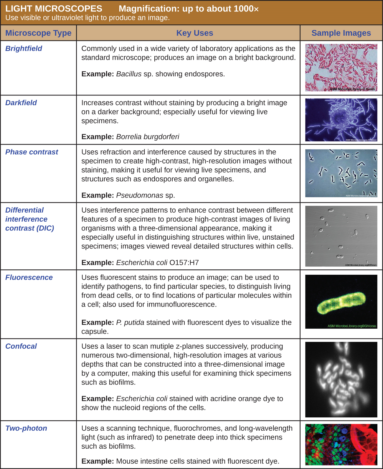
Many types of microscopes autumn under the category of low-cal microscopes, which employ calorie-free to visualize images. Examples of light microscopes include brightfield microscopes, darkfield microscopes, phase-contrast microscopes, differential interference contrast microscopes, fluorescence microscopes, confocal scanning laser microscopes, and two-photon microscopes. These various types of light microscopes can be used to complement each other in diagnostics and research. We will just focus on brightfield, the most mutual type to exist used in labs.
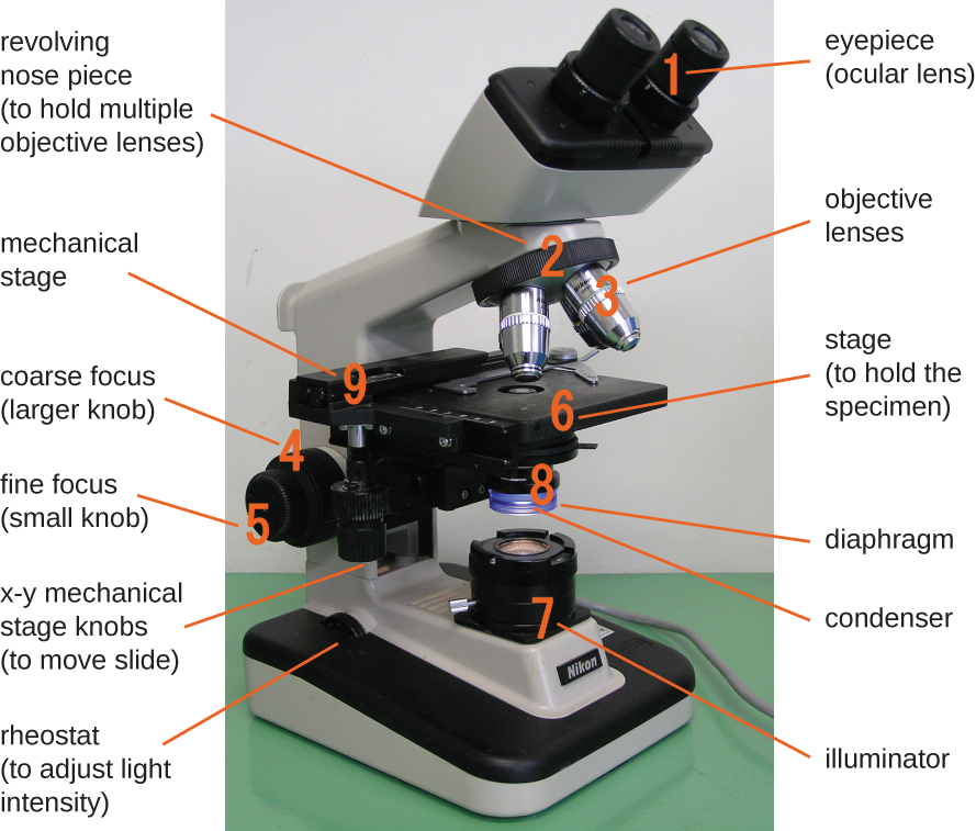
Components of a Typical Brightfield Microscope
The item existence viewed is called a specimen. The specimen is placed on a drinking glass slide, which is and so clipped into place on the stage(a platform) of the microscope. Once the slide is secured, the specimen on the slide is positioned over the lite using the x-y mechanical stage knobs. These knobs movement the slide on the surface of the stage, but practice not enhance or lower the stage. One time the specimen is centered over the light, the stage position tin be raised or lowered to focus the image. The coarse focusing knob is used for large-scale movements with iv⨯ and ten⨯ objective lenses; the fine focusing knob is used for pocket-size-calibration movements, especially with twoscore⨯ or 100⨯ objective lenses.
When images are magnified, they go dimmer because in that location is less light per unit area of image. Highly magnified images produced past microscopes, therefore, require intense lighting. In a brightfield microscope, this lite is provided by an illuminator, which is typically a high-intensity bulb beneath the phase. Light from the illuminator passes upward through condenser lens (located below the stage), which focuses all of the light rays on the specimen to maximize illumination. The position of the condenser can be optimized using the attached condenser focus knob; once the optimal distance is established, the condenser should not be moved to adapt the effulgence. If less-than-maximal low-cal levels are needed, the amount of light striking the specimen can be easily adjusted by opening or closing a diaphragm between the condenser and the specimen. In some cases, brightness tin also be adjusted using the rheostat, a dimmer switch that controls the intensity of the illuminator.
A brightfield microscope creates an image by directing light from the illuminator at the specimen; this light is differentially transmitted, absorbed, reflected, or refracted by unlike structures. Different colors can comport differently as they interact with chromophores (pigments that absorb and reflect particular wavelengths of light) in parts of the specimen. Often, chromophores are artificially added to the specimen using stains, which serve to increase contrast and resolution. In general, structures in the specimen will appear darker, to various extents, than the bright background, creating maximally sharp images at magnifications up to near thousand⨯. Farther magnification would create a larger epitome, but without increased resolution. This allows us to see objects equally pocket-sized every bit bacteria, which are visible at about 400⨯ or so, merely not smaller objects such equally viruses.
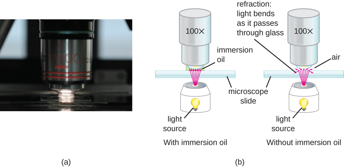
At very loftier magnifications, resolution may exist compromised when light passes through the small-scale corporeality of air betwixt the specimen and the lens. This is due to the large difference between the refractive indices of air and drinking glass; the air scatters the low-cal rays before they can be focused by the lens. To solve this problem, a drop of oil tin be used to fill up the infinite betwixt the specimen and an oil immersion lens, a special lens designed to be used with immersion oils. Since the oil has a refractive index very similar to that of drinking glass, information technology increases the maximum bending at which light leaving the specimen tin strike the lens. This increases the light nerveless and, thus, the resolution of the image (Figure \(\PageIndex{10}\)). A variety of oils can be used for different types of lite.
Brightfield Microscopes
The brightfield microscope, perchance the most commonly used type of microscope, is a compound microscope with two or more lenses that produce a night epitome on a bright background. Some brightfield microscopes are monocular (having a single eyepiece), though near newer brightfield microscopes are binocular (having two eyepieces), like the one shown in Effigy \(\PageIndex{9}\); in either case, each eyepiece contains a lens chosen an ocular lens. The ocular lenses typically magnify images x times (10⨯). At the other terminate of the body tube are a gear up of objective lenses on a rotating nosepiece. The magnification of these objective lenses typically ranges from iv⨯ to 100⨯, with the magnification for each lens designated on the metallic casing of the lens. The ocular and objective lenses work together to create a magnified image. The total magnification is the product of the ocular magnification times the objective magnification:
\[\text{ocular magnification}\; \times\; \text{objective magnification}\]
For example, if a 40⨯ objective lens is selected and the ocular lens is ten⨯, the total magnification would be
(40×)(x×)=400×
Microscope Maintenance: All-time Practices
Even a very powerful microscope cannot evangelize high-resolution images if it is not properly cleaned and maintained. Since lenses are carefully designed and manufactured to refract light with a high degree of precision, fifty-fifty a slightly dirty or scratched lens will refract light in unintended ways, degrading the image of the specimen. In addition, microscopes are rather frail instruments, and great care must be taken to avert damaging parts and surfaces. Amidst other things, proper intendance of a microscope includes the following:
- cleaning the lenses with lens newspaper
- not assuasive lenses to contact the slide (e.g., by rapidly changing the focus)
- protecting the bulb (if there is one) from breakage
- not pushing an objective into a slide
- non using the fibroid focusing knob when using the xl⨯ or greater objective lenses
- only using immersion oil with a specialized oil objective, usually the 100⨯ objective
- cleaning oil from immersion lenses afterwards using the microscope
- cleaning whatever oil accidentally transferred from other lenses
- covering the microscope and/or placing it in a cabinet when non in use
Electron Microscopy
The maximum theoretical resolution of images created past light microscopes is ultimately express past the wavelengths of visible light. Near light microscopes tin only magnify 1000⨯, and a few can magnify upwardly to 1500⨯, merely this does not begin to approach the magnifying ability of an electron microscope (EM), which uses brusque-wavelength electron beams rather than light to increase magnification and resolution.
Electrons, like electromagnetic radiation, can behave as waves, but with wavelengths of 0.005 nm, they can produce much better resolution than visible light. An EM can produce a precipitous image that is magnified upwards to 100,000⨯. Thus, EMs tin resolve subcellular structures every bit well as some molecular structures (e.k., single strands of Deoxyribonucleic acid); however, electron microscopy cannot be used on living material because of the methods needed to prepare the specimens.
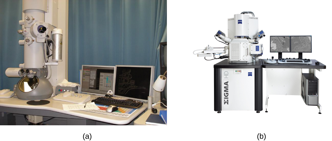
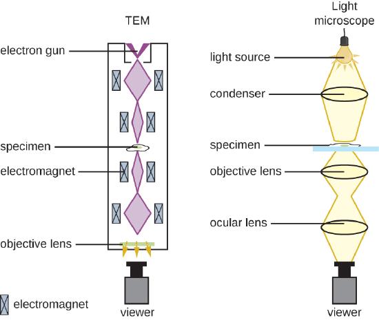
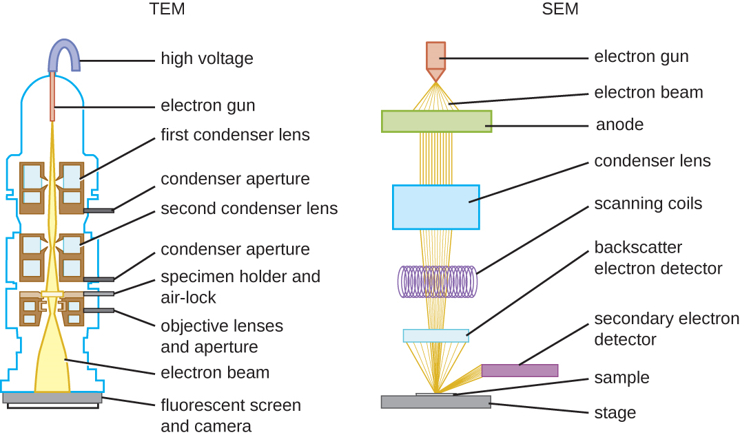
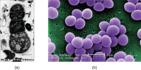
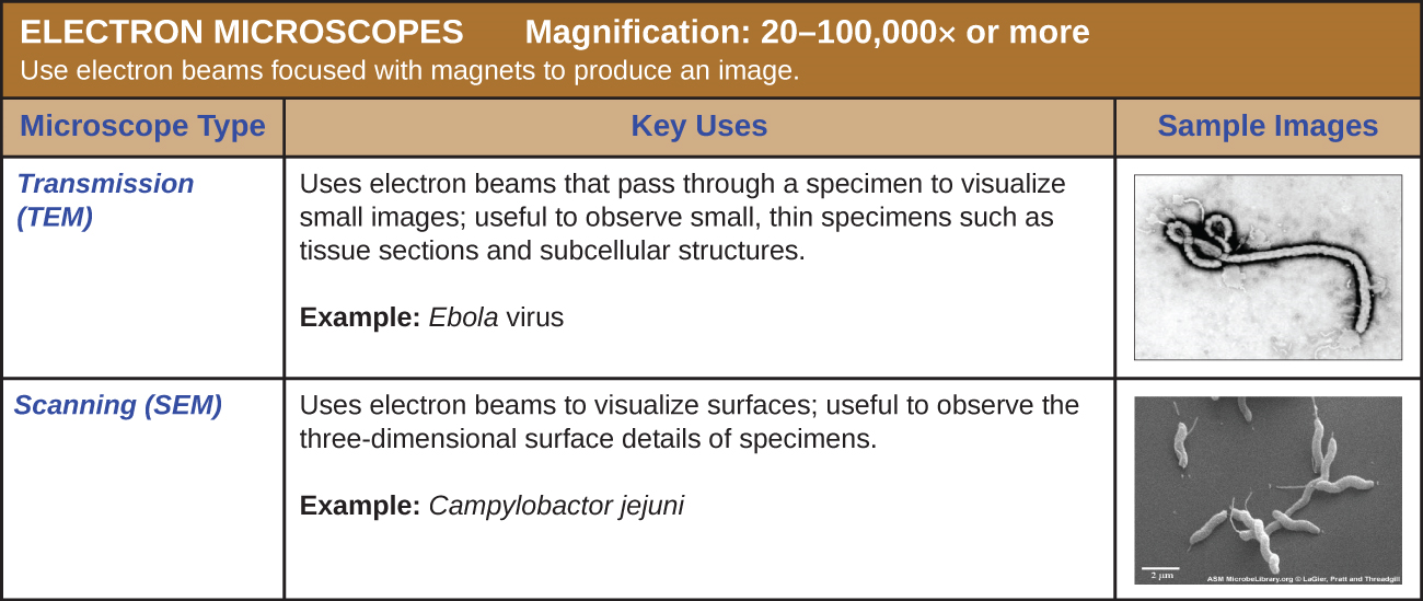
There are two basic types of EM: the transmission electron microscope (TEM) and the scanning electron microscope (SEM)(Effigy \(\PageIndex{11}\)). The TEM is somewhat analogous to the brightfield low-cal microscope in terms of the mode it functions. However, it uses an electron beam from in a higher place the specimen that is focused using a magnetic lens (rather than a glass lens) and projected through the specimen onto a detector. Electrons pass through the specimen, and so the detector captures the image (Figure \(\PageIndex{12}\)).
For electrons to pass through the specimen in a TEM, the specimen must exist extremely thin (20–100 nm thick). The image is produced because of varying opacity in diverse parts of the specimen. This opacity can be enhanced by staining the specimen with materials such as heavy metals, which are electron dense. TEM requires that the beam and specimen be in a vacuum and that the specimen exist very sparse and dehydrated. The specific steps needed to prepare a specimen for observation under an EM are discussed in detail in the side by side section.
SEMs form images of surfaces of specimens, usually from electrons that are knocked off of specimens by a beam of electrons. This tin can create highly detailed images with a three-dimensional appearance that are displayed on a monitor (Figure \(\PageIndex{xiii}\)). Typically, specimens are dried and prepared with fixatives that reduce artifacts, such as shriveling, that can exist produced by drying, earlier existence sputter-coated with a thin layer of metal such every bit gold. Whereas manual electron microscopy requires very thin sections and allows one to meet internal structures such every bit organelles and the interior of membranes, scanning electron microscopy can be used to view the surfaces of larger objects (such as a pollen grain) equally well as the surfaces of very small samples (Figure \(\PageIndex{xiv}\)). Some Ems can magnify an prototype upwards to 2,000,000⨯.1
Exercise \(\PageIndex{6}\)
- What are some advantages and disadvantages of electron microscopy, as opposed to lite microscopy, for examining microbiological specimens?
- What kinds of specimens are all-time examined using TEM? SEM?
Primal Concepts and Summary
- Lite waves interacting with materials may be reflected, absorbed, or transmitted, depending on the properties of the material.
- Light waves can collaborate with each other (interference) or exist distorted by interactions with small objects or openings (diffraction).
- Refraction occurs when light waves alter speed and direction as they pass from one medium to another. Differences in the refraction indices of two materials determine the magnitude of directional changes when low-cal passes from one to the other.
- A lens is a medium with a curved surface that refracts and focuses light to produce an image.
- Visible light is part of the electromagnetic spectrum; light waves of different frequencies and wavelengths are distinguished equally colors past the man eye.
- A prism tin separate the colors of white light (dispersion) because unlike frequencies of light have different refractive indices for a given fabric.
- Fluorescent dyes and phosphorescent materials can effectively transform nonvisible electromagnetic radiation into visible light.
- The power of a microscope can be described in terms of its magnification and resolution.
- Resolution can be increased by shortening wavelength, increasing the numerical aperture of the lens, or using stains that heighten contrast.
- Antonie van Leeuwenhoek is credited with the offset ascertainment of microbes, including protists and leaner, with simple microscopes that he made.
- Robert Hooke was the first to describe what we now call cells.
- Simple microscopes accept a single lens, while compound microscopes have multiple lenses.
- Numerous types of microscopes employ various technologies to generate micrographs. Virtually are useful for a particular blazon of specimen or application.
- Light microscopy uses lenses to focus light on a specimen to produce an image. Unremarkably used light microscopes include brightfield, darkfield, stage-dissimilarity, differential interference contrast, fluorescence, confocal, and two-photon microscopes.
- Electron microscopy focuses electrons on the specimen using magnets, producing much greater magnification than light microscopy. The manual electron microscope (TEM) and scanning electron microscope (SEM) are 2 common forms.
Glossary
- absorbance
- when a molecule captures energy from a photon and vibrates or stretches, using the free energy
- amplitude
- the height of a wave
- brightfield microscope
- a chemical compound light microscope with two lenses; it produces a night image on a bright background
- chromophores
- pigments that absorb and reflect particular wavelengths of lite (giving them a color)
- fibroid focusing knob
- a knob on a microscope that produces relatively large movements to adjust focus
- condenser lens
- a lens on a microscope that focuses light from the light source onto the specimen
- dissimilarity
- visible differences between parts of a microscopic specimen
- compound microscope
- a microscope that uses multiple lenses to focus low-cal from the specimen
- diaphragm
- a component of a microscope; typically consists of a disk under the phase with holes of various sizes; can be adjusted to permit more or less light from the calorie-free source to reach the specimen
- diffraction
- the changing of direction (bending or spreading) that occurs when a light wave interacts with an opening or bulwark
- dispersion
- the separation of low-cal of dissimilar frequencies due to different degrees of refraction
- electron microscope
- a type of microscope that uses curt-wavelength electron beams rather than light to increment magnification and resolution
- fine focusing knob
- a knob on a microscope that produces relatively small movements to accommodate focus
- fluorescent
- the power of certain materials to absorb energy and so immediately release that energy in the form of light
- focal length
- the altitude from the lens to the image indicate when the object is at a definite distance from the lens (this is also the distance to the focal point)
- focal signal
- a property of the lens; the image bespeak when calorie-free inbound the lens is parallel (i.eastward., the object is an infinite altitude from the lens)
- frequency
- the rate of vibration for a lite wave or other electromagnetic wave
Footnotes
- illuminator
- the low-cal source on a microscope
- image point (focus)
- a property of the lens and the distance of the object to the lens; the point at which an prototype is in focus (the image bespeak is often called the focus)
- interference
- distortion of a lite moving ridge due to interaction with another wave
- magnification
- the power of a microscope (or lens) to produce an image that appears larger than the actual specimen, expressed equally a cistron of the actual size
- numerical aperture
- a measure of a lens's ability to assemble light
- objective lenses
- on a light microscope, the lenses closest to the specimen, typically located at the ends of turrets
- ocular lens
- on a microscope, the lens closest to the eye (also called an eyepiece)
- oil immersion lens
- a special objective lens on a microscope designed to exist used with immersion oil to improve resolution
- opacity
- the holding of absorbing or blocking light
- phosphorescence
- the ability of sure materials to blot free energy and and so release that energy every bit lite afterwards a delay
- reflection
- when light bounces dorsum from a surface
- refraction
- bending of lite waves, which occurs when a light wave passes from ane medium to some other
- refractive index
- a measure of the magnitude of slowing of light waves by a particular medium
- resolution
- the ability to distinguish between two points in an image
- rheostat
- a dimmer switch that controls the intensity of the illuminator on a lite microscope
- scanning electron microscope (SEM)
- a blazon of electron microscope that bounces electrons off of the specimen, forming an prototype of the surface
- simple microscope
- a type of microscope with simply one lens to focus lite from the specimen
- stage
- the platform of a microscope on which slides are placed
- total magnification
- in a light microscope is a value calculated by multiplying the magnification of the ocular past the magnification of the objective lenses
- transmission electron microscope (TEM)
- a type of electron microscope that uses an electron axle, focused with magnets, that passes through a thin specimen
- transmittance
- the amount of light that passes through a medium
- transparency
- the belongings of allowing light to laissez passer through
- wavelength
- the distance betwixt 1 pinnacle of a wave and the next height
- x-y mechanical phase knobs
- knobs on a microscope that are used to adjust the position of the specimen on the stage surface, mostly to middle it direct above the lite
- 1 "JEM-ARM200F Transmission Electron Microscope," JEOL U.s. Inc, www.jeolusa.com/PRODUCTS/Tran...specifications. Accessed viii/28/2015.
Contributor
-
Nina Parker, (Shenandoah University), Mark Schneegurt (Wichita State Academy), Anh-Hue Thi Tu (Georgia Southwestern State University), Philip Lister (Central New United mexican states Community College), and Brian K. Forster (Saint Joseph'south University) with many contributing authors. Original content via Openstax (CC BY 4.0; Admission for free at https://openstax.org/books/microbiology/pages/1-introduction)
Source: https://bio.libretexts.org/Courses/Manchester_Community_College_(MCC)/Remix_of_Openstax%3AMicrobiology_by_Parker_Schneegurt_et_al/03%3A_Microscope_and_the_Cell/3.01%3A_The_Properties_of_Light
0 Response to "What Happens to the Light Rays When They Hit the Specimen?"
Post a Comment